MODERN DESIGN OF
FOIL BEARNG AND
ROTOR DYNAMIC SYSTEM
Features:
Detailed Numerical Solution for Reynolds Equation
Advanced Numerical Solutions for 3D Navier-Stokes Equations with Turbulent Flows
Advanced Design of Foil Bearing Components
Probabilistic Robust Design of Bearings and Rotor Dynamics
SBIR Report “IMPROVED ANALYTICAL CAPABILITIES FOR FOIL AIR BEARINGS”
AERO PROPULSION LABORATORY
WRIGHT RESEARCH AND DEVELOPMENT CENTER
January 1990
AUTHOR
Erh-Rong Wu Dr. Eng. Sc. Columbia University, P.E.
www.megaresearch.com
Dr. Erh-Rong Wu is a doctorate graduated from Columbia University, New York.
He joined Shaker Research Corporation leaded by Dr. C.H.T. Pan to develop RSVP (Rotor Substructure Vibration Program) for Wright Aeronautical Laboratories. He worked for Allis-Chalmers Corporation Hydro Turbine Division in charge of rotor bearing system design. He served as an adjunct faculty at Pennsylvania State University, Capitol Campus teaching finite element courses. He joined Garrett AiResearch Corporation Foil Gas bearing group to improve foil bearing design, analysis and manufacturing processes. He founded Mega Research Inc. to develop a multi bearing library and rotor-bearing dynamic codes utilizing probabilistic approaches.
CONTENTS
PREFACE
PART 1. ADVANCED FOIL BEARING DESIGN AND ANALYSIS
1.1 Introduction
1.2 Reynolds Equation Approach
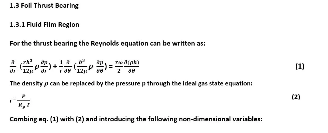
1.3 Foil Thrust Bearing
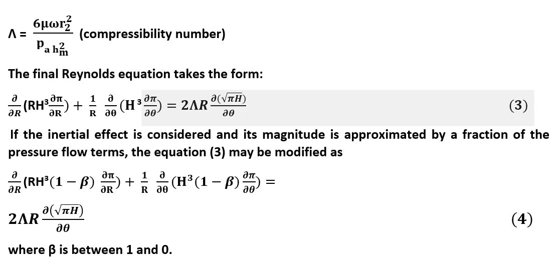
1.3.1 Fluid Film Region
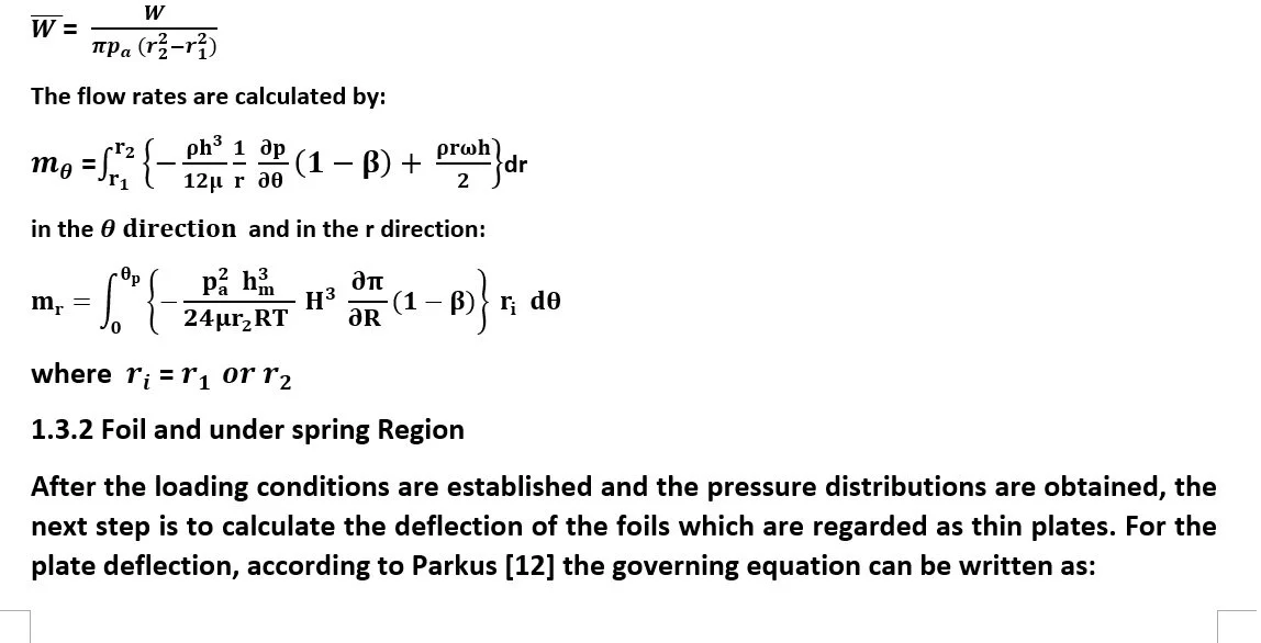
1.3.2 Foil and Underspring Region
1.3.3 Solution Procedure
1.4 Foil Journal Bearing
1.4.1 Fluid Film Region
1.4.2 Fluid Film Profile
1.4.3 Lift-Off Speed and Minimum Film Thickness
1.4.4 Numerical Solution of Reynolds Equation
1.5 Column Method
PART 2. THREE DIMENSIONAL NAVIER-STOKES APPROACH
2.1 Introduction
2.2 Fluid Film Region
2.3 Foil Region
2.4 Numerical Solution
2.5 Computations of Bearing Coefficients
PART3. PROBABILISTIC ROTOR-BEARING DYNAMICS
3.1 Introduction
3.2 Rotor-Bearing Dynamic Analysis
3.3 Field Transfer Matrix
3.4 Station Transfer Matrix
3.5 Rotor-Bearing Dynamic Module
3.6 Probabilistic Approach
3.7 Rotor Model for Computations
3.8 Computations and Results
3.9 First Order Reliability Method for Finding Design Point
3.10 Concluding Remarks
Part 4. ADVANCED DESIGN of Foil Bearing Components
4.1. Journal Foil Bearing Underspring
4.2. Wavy Form Underspring
4.3. Design Processes
4.4. Design Parameters
4.5 Material Spring Back
4.6 Increase of Material Strength
4.6.1 Elastic-Plastic Behavior Of Bearing Underspring
4.7 Design of Foil leaves
PREFACE
This book is intended to provide an advanced and informative reference for foil air/gas bearing analysts, designers and developers. The book consists of basic foil bearing theory, analysis and practice. Furthermore, it gives improved analytical tools for practical applications in design processes.
In the field of lubrication analysis, Reynolds equation approach has been widely employed for liquid lubricant applications where the fluid is incompressible and the governing equation, Reynolds equation, is linear. The solution process is simple and straight forward even with numerical approximations. As for the case of air or gas bearings, the fluid is compressible and the governing equation is nonlinear. Linearization and numerical approximations are needed to perform analysis. The significant features of this book focus on these mentioned numerical solution techniques.
The book contains two topics. The first topic (Part 1 and Part 2) provides detailed solution techniques for Reynolds Equation with well explained numerical procedures. Chapter 1 provides derivations of Reynolds equation for a foil air bearing configuration. Detailed numerical solution procedures utilizing the well-known Column method are provided. The lift-off speed and the fluid film thickness which are essential in foil bearing operations are discussed. Thermal elasticity behavior in the supporting spring region is considered and numerical approaches are employed. Chapter 2 taking the Reynolds number effects into account, three dimensional Navier-Stocks approach is presented. Complete turbulent flow formulations including energy equations are used for the numerical solution with SIMPLE algorism. Special coordinate transformations for fluid film thickness are developed to facilitate numerical formulations. The technical report submitted under SBIR program to Wright Research and Development Center entitled, “Improved Analytical Capabilities for Foil Air Bearings,” is included as in Appendix.
The second topic (Part 3) outlines conventional rotor-bearing dynamic approaches. Then it presents a new probabilistic approach to consider the random behaviors of design variables. The first order reliability method (FORM) is utilized to prevent critical speed encounter and avoid synchronous vibration. This technical tool renders concepts to quickly define design variables for better rotor vibration control.
Part4. offers advanced design processes for foil bearing components. Utilization of numerical formulations to facilitate complex geometry design of essential bearing parts.
The original SBIR report has been retyped and revised. All formulations and pictures are clean and clear.
Erh-Rong Wu
Dr. Eng Sc., PE
Part 1 Advanced Foil Bearing Design and analysis
1.1 Introduction
Compliant foil air bearings have been preferable candidates for supporting high speed gas turbine rotors. The foil bearings have been recognized to have advantages, in comparison with conventional rigid air bearings, such as (i) higher load carrying capacity, (ii) better dynamic stability, (iii) tolerance of shaft misalignment and (iv) tolerance of foreign matters. These advantageous features result from the flexibility of the foils, the bearing preload and physical configuration of supporting top and bottom foils.
The geometrical configurations of typical foil air bearings consist of
Thrust bearing: Multiple supporting pads with top foils attached at the leading edges. Underneath the top foil there is a bump structure (AiResearch) [1] or corrugated bottom spring (MTI)[2][3] to increase stiffness.
Journal bearing: Basically there are two types:
First there is a single top foil or two conjugate top foils with a single bump bottom spring.
Second there are multiple top foils either separated or overlapped with preload capability. The bottom sprig is either in bump or wavy form.
There are analytical studies which provide tools for analyzing bearing performances and guidelines for bearing design. The analytical approaches can be categorized as (i) Reynolds equation approach [4] [5] and (ii) 3D Navier Stokes equations approach [6]. Due to the complex bearing geometry and the nonlinearity of governing equations, the Reynolds equation approach has been the most widely used tool for many years. However, issues of great importance concerning high speed rotors have not been properly addressed. The issues are: (1) turbulent fluid films, (2) flow inertial effects, (3) thermal-fluid and thermal-elasticity effects and (4) bearing rotor dynamics. The first three issues result from the trend in requiring rotors to operate at high speeds. The last issue actually can be resolved by combining a competent foil bearing computer code with a rotor dynamic code. The first three issues have been well studied [7][8][9][10][11] in rigid bearings. Nevertheless for foil bearings
with compliant surfaces, studies remain inside the realm of the conventional Reynolds equation approach which may not be suitable for the foil bearings.
Most foil bearings are expected to operate at speeds higher than 35,000 RPM. For gas turbine rotors, a shaft diameter of 5 inches is not uncommon and an average bearing radial clearance of 0.006 inches is a reasonable estimate. Therefore, the Reynolds number for air at 100 degree Fahrenheit is about 2100. According to Taylor instability for the flow between two cylinders, the turbulence on-set criterion is Re>41.1(R/C); R is the radius of the rotating cylinder; the outer cylinder is stationary; C is the clearance. The critical Re is 839 for the bearing geometry considered. Even based on the general internal flow the turbulence criterion, the critical Re is 2000. Obviously, the flow in a high speed foil bearing is most likely a turbulent flow.
In addition to the turbulence, the inertia plays an important role in interfacing the fluid film, the inner region, with the ambience, the external region. The inertial effect becomes more pronounced when there are pockets in the film or the bearing surface is flexible.
As the rotor speed increases, the fluid film temperature increases accordingly. The energy transport in the turbulent flow becomes significant; the traditional assumption of isothermal fluid film is no longer appropriate. Since the temperature can be very high, the thermal expansion of the foil can not be neglected.
To resolve the above-mentioned issues the 3D Navier-Stokes equations with temperature variation considered is a more desirable approach. Nevertheless, the Reynolds equation merits in handling
Laminar flow films cannot be ignored. Consequently, this book comprises the Reynolds equation approach and 3D Navier-Stokes approach. The SBIR technical report is included as Appendix.
In the real world there are uncertainties in design and manufacturing processes. Design parameters are realistically not constants as conventional so-called deterministic approach practices. To take the uncertainty into account, the probabilistic approach recognizes design parameters as random variables. Each design variable is represented by a probability distribution function (PDF) which is established by using available historical data or by statistical functions. A limit state function or target function is defined. The bearing design programs with input random variable functions to obtain a set of robust design parameters which are closest to the target such as bearing carrying load capacity or altitude angle with least variations.
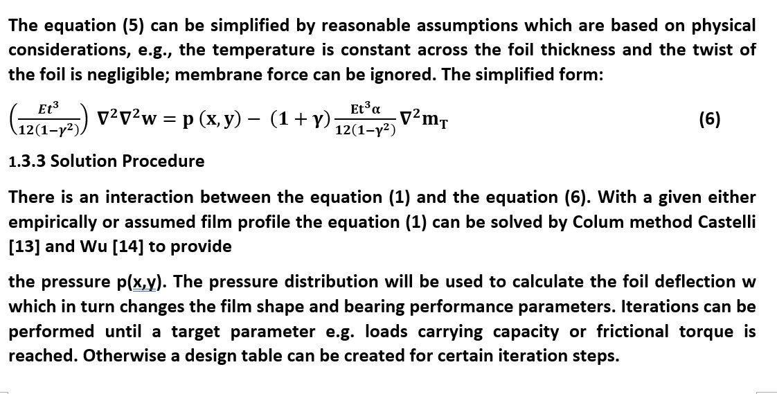
Design parameters will be represented by their probability density functions or probability distribution functions (PDF) which are created by the histograms of design parameter occurrences or available data associated with existing products. Robust design indicates that both the limit state function and its variation approach zeros. In the following Fig 1 depicts the concept of variation in the robust design process. The robust design may use analytical algorithm to execute iteration process to obtain the design point. The iteration begins from design 1 continuing to design 2 until design 3 where the target point is reached and the standard deviation approaches zero. Details will be revealed in Part 3.
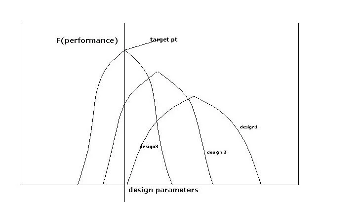
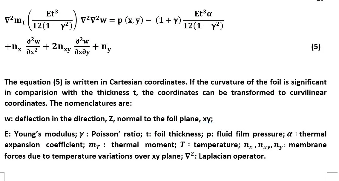
Fig. 1 Robust Design Process
1.2 Reynolds Equation Approach
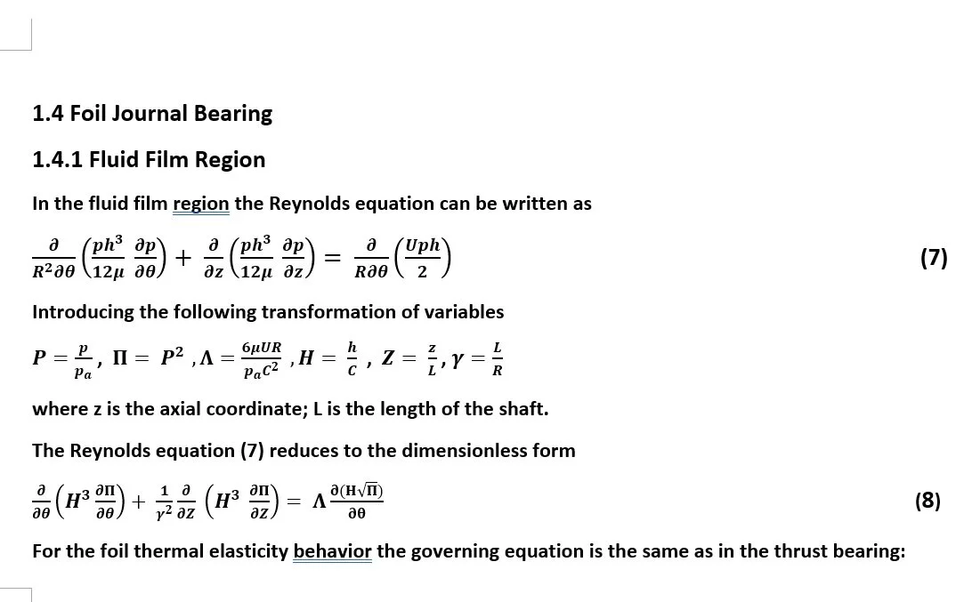
1.2.1 Fluid Film Region
Reynolds equation has been widely used as the governing equation of the fluid film region. Assumptions used by the Reynolds equation are:
Inertial force is negligible.
Flow across the film gap is insignificant.
Reynolds number of the fluid flow is small (Re˂ 2000).
The Reynolds equation approach can be applied to both thrust bearings and journal bearings.
Fig. 1A, B depicts a typical foil thrust bearing while Fig. 2A, B shows a journal foil bearing geometry.
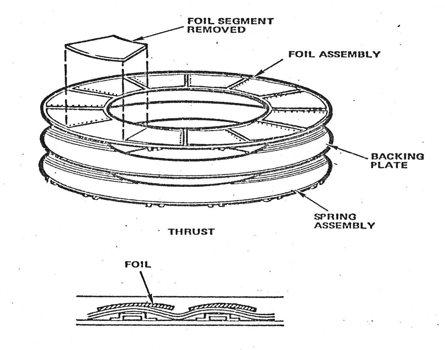
Fig 1A Foil Thrust Bearing Components
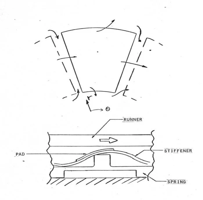
Fig 1B Thrust Bearing Geometry
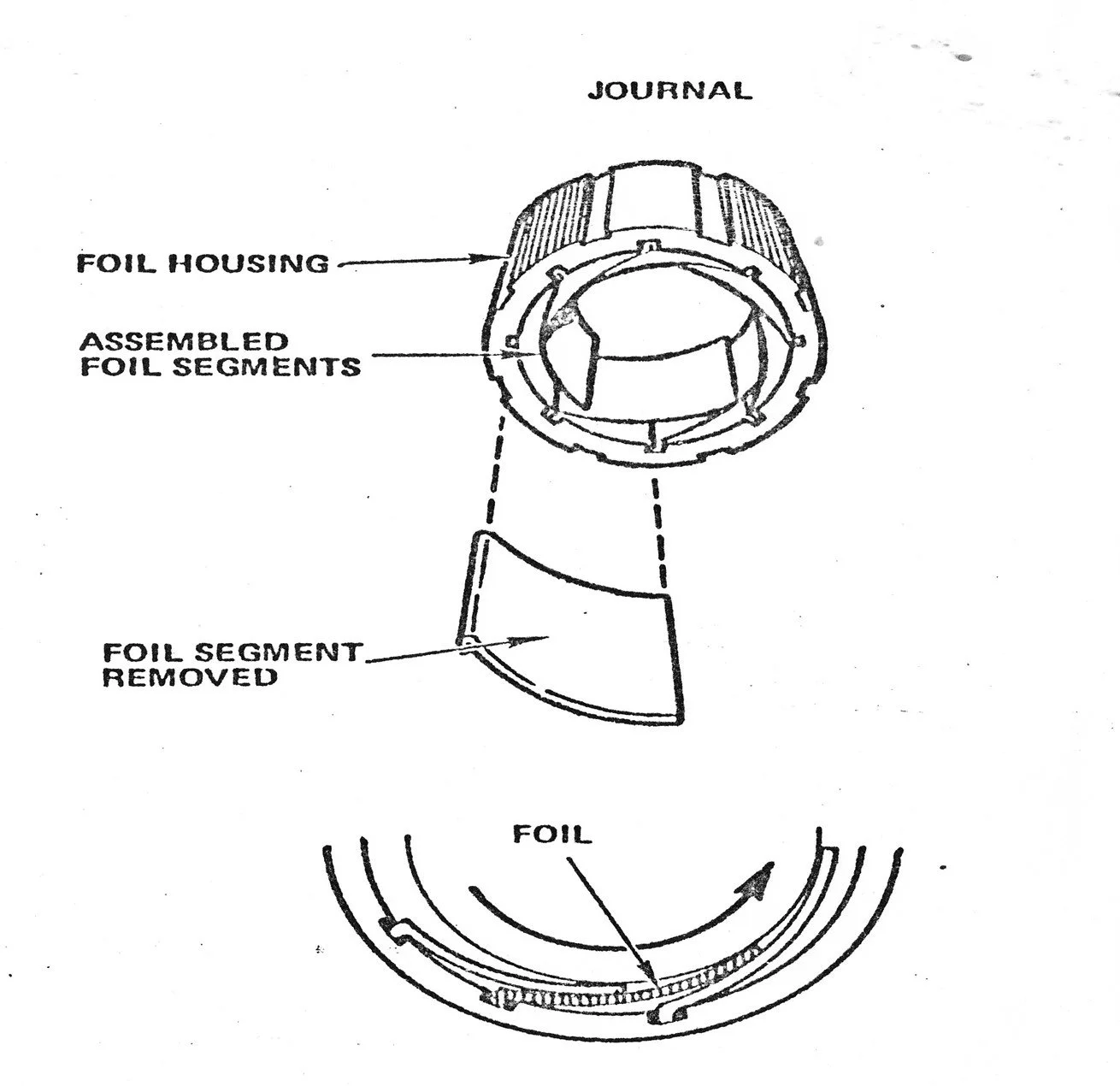
Fig 2A Foil Journal Bearing Components
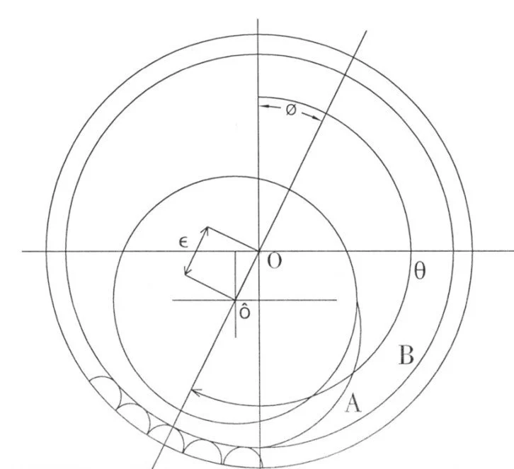
Fig.2B Journal Bearing Geometry